
Servo Motor
DC servo motor:
AC servo motor:
Brushless DC servo motor:
Positional rotation servo motor:
Continuous rotation servo motor:
Linear servo motor:
Raspberry Pi:
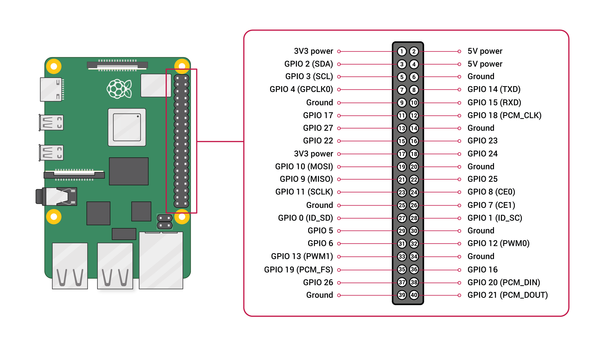
Pin configuration:
1. Vin: Two 5v pins and two 3v3 pins used for providing power supply, where processor works on 3.3v.

import RPi.GPIO as GPIO
import time

servoPIN = 17
GPIO.setmode(GPIO.BCM)
GPIO.setup(servoPIN, GPIO.OUT)

p = GPIO.PWM(servoPIN, 50) # GPIO 17 for PWM with 50Hz
p.start(2.5) # Initialization
try:
  while True:
    p.ChangeDutyCycle(5)
    time.sleep(0.5)
    p.ChangeDutyCycle(7.5)
    time.sleep(0.5)
    p.ChangeDutyCycle(10)
    time.sleep(0.5)
    p.ChangeDutyCycle(12.5)
    time.sleep(0.5)
    p.ChangeDutyCycle(10)
    time.sleep(0.5)
    p.ChangeDutyCycle(7.5)
    time.sleep(0.5)
    p.ChangeDutyCycle(5)
    time.sleep(0.5)
    p.ChangeDutyCycle(2.5)
    time.sleep(0.5)
except KeyboardInterrupt:
  p.stop()
  GPIO.cleanup()